Rolling Your Own:
building antenna splitters that perform better
than most commercial units
by John Bryant and Bill Bowers
About nine months
ago, Bill Bowers and I began what became a rather
thorough study of signal splitters. From the beginning,
we had hoped to develop a splitter design for
homebrewing that would perform as well or better
than the rather expensive units currently available
on the commercial market.
Our first steps
were to purchase the three two-port splitters
currently available in North America and for Bill
to take them through a sophisticated series of
tests. The three units tested were:
1) Model MC-102, Stridsberg.
The 2004 retail price was $65 plus S&H.
2) Model SP-1, RF Systems, available from
several hobby sources around the world. Our test
unit was purchased from Universal
Radio. The retail price in 2004 was $89.95 plus
S&H.
3) Model ZSC-2-2 Mini-Circuits. Our unit
was purchased directly from the Mini-Circuit sales
office in Missouri (phone: +1-718-934-4500) for
$52.95 plus S&H in 2004.
Those initial tests were widely
published in May 2004 as An
Evaluation of Commercially Available Signal Splitters.
In brief, the findings were that all three units
were quite adequate signal splitters and that -
for all but the most demanding applications - we
recommended selecting commercial units based on
price and availability. We also noted that the Mini-Circuits
Model ZSC-2-2 out-performed the other two units,
at least slightly, in every single test. It was
also the least expensive, at $52.95 for the two-port
version.
The data developed during those
tests established the current state-of-the-art for
the next design cycle. Those same results are presented
in this article along with the test results for
the new design that we suggest for DXers who wish
to "roll their own" and save a good bit
of "radio money" in the process.
Why Do I Need
a Signal Splitter, Anyway?
In recent years, increasing numbers
of radio hobbyists have wished to attach multiple
receivers to the same antenna. This need may stem
from a group wishing to share a single antenna on
a DXpedition, or it may be from a single hobbyist
wishing to operate two or more receivers simultaneously
from the same antenna. In any case, many of us have
found that simply using a stub of wire to hook the
antenna ports of several receivers to the same antenna
is an invitation to all sorts of problems. One of
the funnier problems can occur if one of several
receivers hooked together presents significantly
lower impedance to the antenna than do the others.
Years ago, when Mitch Sams, Kirk
Allen and John Bryant first "shared" a
beverage antenna, Kirk and John spent a frustrating
half-night wondering why Mitch's old receiver was
so much superior to their more modern gear: they
eventually realized that Mitch's old receiver was
literally sucking up all of their DX! A second common
occurrence when hooking multiple receivers together
is the fact that spurious radiations/local oscillator
signals from one receiver can use the common antenna
lead as a pathway to enter the other receivers;
this can cause serious but difficult to recognize
interference, strange "signals," etc.
For all of these reasons and more, if you wish to
operate two or more receivers - simultaneously -
from one antenna, you will need to use a device
called variously, an antenna splitter, a signal
splitter or a power splitter: when referring
to a receiving antenna device, most people use these
three terms interchangeably.
What the Heck
Are They?
The first antenna
splitters that many of us saw were rather expensive
and complex devices built with vacuum tube technology.
These devices were usually purchased as used-surplus
from government surplus property outlets and often
support 8 or 16 receivers simultaneously and contained
sophisticated RF amplifiers, as well.
 In
more recent times, smaller-scale splitters have
become available commercially, intended for both
the professional and serious hobbyist markets. The
most commonly available splitters are 2-port, unamplified
units. However, 4-port units, either with or without
solid state amplifiers, are also available and two
of the three splitter manufacturers produce a bewildering
array of splitters suited for many professional
communications uses. Military and intelligence agencies
are known to have contracted with manufacturers
to produce modern units with at least as many as
many as 32 ports. These have recently appeared on
the used-surplus market, as well. In
more recent times, smaller-scale splitters have
become available commercially, intended for both
the professional and serious hobbyist markets. The
most commonly available splitters are 2-port, unamplified
units. However, 4-port units, either with or without
solid state amplifiers, are also available and two
of the three splitter manufacturers produce a bewildering
array of splitters suited for many professional
communications uses. Military and intelligence agencies
are known to have contracted with manufacturers
to produce modern units with at least as many as
many as 32 ports. These have recently appeared on
the used-surplus market, as well.
 Most
signal splitters are based on a fundamental building
block which is a transformer-like device that accepts
a single signal stream and splits it into two identical
parts that are each (by the laws of physics)
diminished in strength by about 3 dB, minimum.
Usually, these transformer-like devices consist
of a ferrite core with windings of fine wire; this
building block may be diagrammed as an upside-down
capital letter "Y." Most
signal splitters are based on a fundamental building
block which is a transformer-like device that accepts
a single signal stream and splits it into two identical
parts that are each (by the laws of physics)
diminished in strength by about 3 dB, minimum.
Usually, these transformer-like devices consist
of a ferrite core with windings of fine wire; this
building block may be diagrammed as an upside-down
capital letter "Y."
 Antenna
splitters that offer four output ports contain three
"building blocks" arranged in a cascade
fashion, where the first unit splits the signal
into two halves, which are then fed into a second
rank of two splitters; those second rank splitters
divide the half signals into halves again, creating
four identical signals of further diminished strength.
Since each transformation/splitting incurs about
3 dB of loss, it is easy to see why most splitters
of four output ports or more include RF amplification. Antenna
splitters that offer four output ports contain three
"building blocks" arranged in a cascade
fashion, where the first unit splits the signal
into two halves, which are then fed into a second
rank of two splitters; those second rank splitters
divide the half signals into halves again, creating
four identical signals of further diminished strength.
Since each transformation/splitting incurs about
3 dB of loss, it is easy to see why most splitters
of four output ports or more include RF amplification.
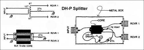
The "DH-P"
Homebrew Splitter
The so-called DH-P
homebrew splitter first surfaced in an article the
early 1980s by Down Under DX enthusiast Sam Dellitt.
The article was first published in DX Australia
and later reprinted in Canada's CIDX Messenger;
a version of it was also featured in an article
in the Proceedings of Fine Tuning (Proc.
1989, article F-12, p.5) by Nick Hall-Patch. The
original core used by Sam has not been available
for years and, in the Proceedings article, Nick
suggested using the "binocular" core,
BLN 73-202 by Amidon. This latter core is the one
used in the tests shown later in this article. The
wire is #30 or #32 varnished magnet wire which requires
a bit of a delicate touch; unfortunately, larger
wire sizes won't fit through the holes enough times
to create the proper turns count for this design.
The New "BB"
Homebrew Splitter
As you will note
in the test results presented later, John Bryant's
twenty year-old DH-P splitter, a veteran of numerous
DXpeditions, performed surprisingly well. In fact,
it out-performed both the RF Systems and Stridsberg
units at most frequencies! The performance of the
DH-P splitter formed the base line for Bill's design
development and testing cycles. He hoped to be able
to out-do the older homebrew and approach the outstanding
performance of the Mini-Circuits splitter.
Both Bill and I
tend to favor winding cores that are about 1"
in diameter or more. The ease of winding these larger
cores more than offsets the small additional cost.
However, after several series of design/testing,
Bill was rather surprised to find that, for this
application, smaller cores were clearly superior!
From that point, Bill focused on designing a splitter
based on Amidon's FT-50J, a toroidal core of about
½" outside and ¼" inside
diameters.
Several additional design/testing
cycles lead Bill to a winding pattern and turns
count quite similar to the DH-P homebrew splitter.
The winding design that Bill suggests is a 21 turn
"primary" from the antenna side of things.
That winding is to be laid on the core first in
an evenly distributed pattern around the circumference
of the toroid. The secondary coil is 14 bi-filar
turns, also distributed evenly around the toroid
(imagine a twisted pair of one red and one blue
wire.) From the two ends, one red and the opposite
blue are tied together and grounded through a 27
Ohm resistor. You have just created a 28-turn secondary
with a center tap to ground through the resistor.
The remaining red and blue wire go, one each to
the center conductor of the two output ports. Please
be sure to follow the wiring diagram with particular
care: John managed to connect the wrong red and
blue wires together on four-out-of-four of the first
prototype splitter series!

"BB" Splitter Transformer
Pictorial
Mount in RF-tight metal enclosure
"BB"
Splitter Fabrication
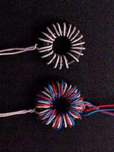 Core:
Amidon FT-50J Core:
Amidon FT-50J
Wire: #30 awg Kynar insulated
Primary: 21 Turns (evenly distributed)
Secondary:14 Turns (refer to diagram)
NOTES:
1) Count as a turn each time the wire goes through
the hole.
2) It is often handy to secure each layer of winding
with "super" glue.
3) Use about one twist per inch for the bifilar
winding. Total length of each winding: about 20."
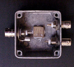
The "BB-2" Splitter: Two Port Unit
For splitters and
most other accessories in the signal stream, it
is necessary to use RF-tight metal enclosures to
minimize the intrusion of stray RF and unwanted
noise. John favors the die-cast cast aluminum boxes
by Hammond that are available from many electronics
outlets, including Mouser.
The box shown above is the Hammond 1590LB, their
smallest box at 2"x2"x1". It cost
$7.22 from Mouser in 2005. The beautiful satin-black
powder-coated version, #1590LB-BK costs $2.50 more.
The BNC chassis-mount connectors, also from Mouser,
did not come with ground lugs, so John utilized
3/8" diameter ring connectors from automotive
electrical systems (note the grounding lug on inside
left of box.)
Note also that John
has glued a small piece of Bakelite (1/2"x1/2"x1/4")
on the bottom of the Hammond box to serve as a insulating
mounting platform for the wound core (see end note
1). The white substance on the interior of the right-hand
box is an epoxy paste made by Protective Coating
Company of Allentown, PA, USA. The white version
is marketed as "PC-11" while a dark gray
version is sold as "PC-7." (Google: PC-7
epoxy) John now applies this to the backside of
most chassis mounts to stabilize them permanently.
Unlike "super" glue and numerous other
fixes, neither PC-7 nor PC-11 have ever failed in
the field.
The "BB-4"
Splitter: Four Port Unit
 It
is possible, of course, to fabricate four-port splitters
using somewhat larger Hammond boxes. However, it
is often possible to find new or slightly used four-port
splitters intended for VHF bands, but utilizing
standard BNC connectors. Such was the case with
the box and ports on the left. John obtained five
of these beauties new for just over $5.00 each through
an on-line auction: less than the cost of the BNC
connectors alone. The three transformers are mounted
to perf board and, in turn the perf board is mounted
to ¼" stand-offs with PC-11 epoxy paste.
The resistors for each of the splitters may be seen
end-on, directly to the right of each core. Total
cost for this particular 4-port splitter was under
$10.00, a 80 to 90% savings of "radio money." It
is possible, of course, to fabricate four-port splitters
using somewhat larger Hammond boxes. However, it
is often possible to find new or slightly used four-port
splitters intended for VHF bands, but utilizing
standard BNC connectors. Such was the case with
the box and ports on the left. John obtained five
of these beauties new for just over $5.00 each through
an on-line auction: less than the cost of the BNC
connectors alone. The three transformers are mounted
to perf board and, in turn the perf board is mounted
to ¼" stand-offs with PC-11 epoxy paste.
The resistors for each of the splitters may be seen
end-on, directly to the right of each core. Total
cost for this particular 4-port splitter was under
$10.00, a 80 to 90% savings of "radio money."
The Tests
Rolling your own splitters is
all well and good, but our real concern, of course,
is distributing precious DX signals equally
to two or four receivers with as little loss
and as little coupling from one receiver to another
as possible. The only way to clearly determine
our success or failure in this effort was to run
a series of comparative bench tests exactly as we
had done in our previous article on commercial splitters.
The test equipment used was: HP-4192A, LF Impedance
Analyzer; HP-11048C, Thru-put 50 Ohm terminator;
AG-04192-61001, Power splitter-50 Ohm; and Fluke-8505A
RF multimeter. The test voltage was 0.10Volt RMS.
The test instrumentation covered the frequency ranges,
150 kHz to 13 MHz, so our 11 test points fell within
that range. We believe that it is safe to extrapolate
the results up to 15 or 20 MHz to cover most of
the bands of interest to our readers.
The following characteristics
were measured over a range of frequencies from 150
kHz to 13 MHz: Antenna Impedance Match, Receiver
Impedance Match, Signal Isolation, Impedance Isolation
and Signal Attenuation. The test data from our previous
article on commercial splitters are included for
comparison purposes. The two "proof of design"
splitters that were bench tested here are the two
shown previously in this article.
ANTENNA IMPEDANCE
MATCH (see end note 2): This is the impedance
that will terminate the coax lead-in cable from
the antenna. The RG-58 has a characteristic impedance
of approximately 50 Ohms and if the antenna port
of the splitter has an impedance other than 50 Ohms,
part of the signal will be reflected back to the
antenna. The greater the impedance of the antenna
port differs from 50 Ohms, the greater will be the
signal loss. The amount of loss is rather complex
and the total loss also depends on the length and
attenuation of the coax. This impedance was measured
at the antenna port with all receiver ports terminated
in 50 Ohms, resistive. The ideal splitter would
present 50 Ohms at the antenna port.

RECEIVER IMPEDANCE MATCH:
This impedance, in an ideal splitter, should
also be 50 Ohms to match the 50 Ohm impedance of
the receiver antenna terminal. The mismatch
here is not quite as important as there is usually
a very short cable between the splitter and the
receiver. Further, The 50 Ohm input impedance of
the receiver is often fairly well defined over a
certain bandwidth. This measurement was made at
a receiver port when the other receiver port and
the antenna port terminated in 50 Ohms, resistive.

SIGNAL ISOLATION: The
local oscillator of a receiver radiates back out
the antenna connection and thus into the splitter.
To prevent one receiver's oscillator from interfering
with the signal going into the other receiver connected
to the splitter, it is desirable to have as much
signal isolation as possible. The larger the
signal isolation, the better. For this test,
the attenuation, from a 50 Ohm source connected
to a receiver port, was measured at another receiver
port. All receiver ports and the antenna port were
terminated in 50 Ohms, resistive.
IMPEDANCE ISOLATION: The
antenna input impedance of a receiver with a "coax
connection" is nominally 50 Ohms when it is
tuned to the incoming signal. Some receivers show
an impedance as low as 10 Ohms at frequencies other
than the one to which the receiver is tuned. This
10 Ohm load at one receiver port of the splitter
can upset the impedance seen at the other port.
Here again the ideal splitter would continue
to present 50 Ohms impedance even when the other
port is loaded with 10 Ohms. This measurement
was made at one receiver port as the impedance at
one of the other receiver ports was reduced from
50 to 10 Ohms, resistive.

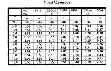
SIGNAL ATTENUATION: This
tabulates the attenuation of a signal, from a 50
Ohm source, as it passes from the antenna port of
the splitter out through one of the receiver ports.
The other receiver port(s) are terminated in 50
Ohms, resistive. The attenuation of a signal
when it is split 2 ways, by an ideal splitter, would
be 3db, when split 4 ways is 6 db, etc. Refer
to Appendix for a description of the methods of
measuring these important values
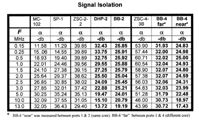
Discussion
We were gratified
with the test results. First, considering Impedance
Matching to both the antenna and the receiver, below
5 MHz the BB-2, the BB-4 and the DHP-2 performed
considerably better than the Stridsberg and RF Systems
units. The new BB homebrew design was somewhat better
than the older DHP unit and even out-performed the
Mini-Circuits unit at some frequencies. The same
general results were obtained when testing for Isolation:
both homebrew designs substantially out-performed
the Stridsberg and RF Systems splitters and the
new BB designs actually outperformed the really
excellent Mini-Circuits design, in a number of instances.
Finally, in the important Signal Attenuation test,
the homebrew units proved superior to the commercial
units in many instances.
Although all three commercial
units out-performed the homebrew units as the test
frequency climbed above 5 MHz, the differences in
both Isolation and Signal Attenuation, even at 13
MHz amounted to a worst-case of 2.3 dB for the DHP
design, .13 dB for the BB-2 and less than a full
dB for the BB-4.
Almost certainly, the performance
of these units could be improved in several ways.
It is possible that both Isolation and Attenuation
could be improved by using slightly larger boxes.
This is particularly true in the case of the BB-4.
The VHF splitters used very small cores and thus
the boxes that John obtained so cheaply were less
than .75 inch deep. These small tolerances between
the larger FT-50 cores and the box may have caused
some capacitive coupling. The tight quarters also
prevented John from arranging the three cores at
90 degrees from each other as is standard practice.
It would be better to arrange the BB-4 cores at
90 degrees ( O __ l as viewed from above .) Our
design goal was to create a homebrew unit that would
perform at LW, MW and SW frequencies. If our goal
was to only serve the shortwave frequencies - 3
to 30 MHz - a different core material might have
improved performance above 5 MHz.
As we noted in the article on
commercial splitters, we were both surprised at
the impedance characteristics exhibited by both
the Stridsberg MC-102 and RF Systems SP-1 in the
tests of Antenna Impedance Match, Receiver Impedance
Match and Impedance Isolation. In some cases, these
mismatches reached 100%. However, the measured
signal losses of all five 2-port units and the two
4-port splitters are very nearly equal, reminding
us again how forgiving receiving-only devices are
of mismatches.
If your "radio time"
is extremely limited, you may want to invest in
one or more of the commercial splitters covered
by our earlier testing. If you have just a modest
amount of time, rolling your own signal splitters
is child's play that you can do as "busy work"
while also involved with other activities. John
wound his twenty transformers during his wife's
driving shifts across Arizona and New Mexico recently
and fabricated the splitters themselves while watching
various year-end football bowl games; he estimates
that he was saving about $40 per hour of "work,"
building five of the 4-way splitters and five of
the 2-way models. Give it a try…. its fun rolling
your own!
APPENDIX
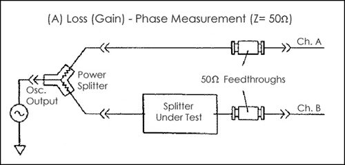
To measure the insertion
loss of the splitter, the oscillator output of the
HP-4192A LF Impedance Analyzer was fed into a power
splitter that split the signal two equal parts.
One of the resulting signals passes through a 50
Ohm feedthrough and goes directly to Channel A.
The other signal goes to the antenna terminal of
the splitter under test and the signal from a receiver
output terminal goes through a 50 ohm feed-through
to Channel B of the HP-4192A. The HP-4192A compares
the signals from A and B and calculates and displays
the signal loss resulting from the signal passing
through the splitter.
End notes
1) Although the enclosure for
the two-port unit was aluminum and magnetically neutral,
there is still some possibility of capacitive coupling
between the windings and the enclosure at higher frequencies,
so an insulating block/mounting pedestal is a reasonable
idea. The enclosures for the four-port units that
John built were heavy-gage sheet steel and, therefore,
even more likely to cause some degradation of performance
were the cores not separated from the enclosure with
an insulating block. It is interesting to note that
Mini-Circuits is very careful to isolate the cores
from their aluminum enclosures and to arrange them
in an arrangement that generates the least interaction
between them: at 90 degrees (O __ l as viewed from
above.) They also maintained the shortest possible
leads from component-to-component by placing all ports
on a single surface of the enclosure and mounting
the printed circuit board directly to the rear ends
of the chassis-mount BNC ports. Each of these design
decisions could contribute to the outstanding and
relatively broad-banded performance of the Mini-Circuits
splitters.
2) The measured values of
Z were actually complex, not purely resistive. The
impedance phase angles were, however, very small
in most cases, and we feel that including those
angles would have been more confusing than helpful.
For instance, the largest impedance phase angle
for the Mini-Circuit ZSC-2-2 was less than 2 degrees
over the entire frequency range. For all practical
purposes, the tabulated values of Z can be considered
resistive.
published on DXing.info
on January 31, 2005
  
|