|
Pre-Amp Peregrinations
Adventures with RF Pre-Amps by Advanced Receiver
Research and DX Engineering
John H.
Bryant and Mark Connelly
1. JOHN'S EXPERIENCE
For many years,
I have been ambivalent about using RF preamplifiers
in my receiving chain.... I have felt that, most
of the time, they only amplify both the noise and
the signal equally, accomplishing nothing but generating
more movement on my S-meter. However, in recent
years, my ideas have been changing. I was first
introduced to modern pre-amps by Don Nelson, when
he used the highly regarded preamps from Advanced
Receiver Research (AR2) to more than overcome the
inherent losses in our 8-way antenna splitters at
the Grayland DXpedition site.
 |
When I began experimenting
with relatively small-sized flags and pennant antennas,
I found that having some pre-amplification often
resulted in a better signal, with more recovered
audio. Naturally, I adopted the AR2
unit (Special Frequency Range, $79.95 USD).
Truth be told, I found it cumbersome to insert the
AR2 unit in my receiving outfit.... For DC power,
this pre-amp required hardwiring rather than the
normal coaxial power plug. Further, and more importantly,
the AR2 preamp had neither a power switch nor a
bypass relay.... It was either in the circuit or
it was out... taking a major operation of lead-in
switching just to add or subtract it from incoming
signals.
 |
I decided that what I really
wanted was a pre-amp of the quality of the AR2 unit
that could stay in the receiver chain all the time,
but which I could invoke or remove from the actual
receiving circuit with the flip of a switch. Truth
be known, I would rather DX without a pre-amp, but
when the signal is in the mud or fading away at
local dawn, I wanted to be able to flip a switch
and "kick it in the butt" with 10-20 dB
of preamplification. If that kick helped, I'd leave
it in the line; if not, it would come right back
out. I finally went so far as to put one of the
AR2 amps in a larger cast aluminum box along with
a bypass relay, LED power indicator, power switch
and coaxial power plug. That amounted to about $30.00
of additional parts and around 6 to 8 hours of bench
time, but it worked like a charm!!! I was quickly
addicted and found the AR2 pre-amp more useful than
I expected. I even found that it would improve signal
to noise ratios on my beverage antennas, but only
at band fade.
As luck would have it, when I
returned to my favorite DXpedition haunts in the
Northwest this spring, I was horrified to find that
the AR2 pre-amp was deader than the proverbial doornail.
I'm not quite sure what happened, but I doubt that
it was the fault of the AR2 unit; the ones at Grayland
have been performing like Trojans for years, with
nary a single failure. Unfortunately, my long-time
spare AR2 preamp is sitting on my work bench at
our other home in Oklahoma, 2250 miles to our southeast!
Recently, I noticed that Mark Connelly, well-known
designer of homebrew phasers and pre-amps, had favorably
mentioned a new commercial unit in several venues:
the RPA-1 by DX Engineering. If Mark liked it, I
thought that I would give it a look on the web:
I was very impressed! The description
of the amp started out:
This is the best HF low-noise amplifier available.
The RPA-1 is optimized for 0.3-35 MHz operating
range. Its push-pull amplifier design and robust
components enable it to with stand high signal levels
and operate when you need it most.
 |
Wow! Making that kind of statement
in the small community of radio enthusiasts means
one of two things. Either a) the company is totally
unscrupulous or b) the gear is really great!
As I read further, I continued to be impressed.
Beside the push-pull design and an internal by-pass
relay, the amp came with an extensive manual that
also outlined several easy modifications which would
allow the user to reduce the gain in stages, if
necessary for a particular application. Unfortunately,
since the RPA-1 is designed for mounting either
at the operator's position or at the feed point
of the antenna, the unit did not come with either
a power switch or an LED power indicator. Also,
since the unit was apparently intended for those
radio amateurs who use 75 ohm feed line, the antenna
input and output ports were F-type connectors, supplemented
by paralleled RCA jacks (!!!) Like all communications
receivers and most listener-DXers, long ago, I committed
to 50 ohm feed line and, in my case, BNC-connectors.
 |
Happily, I knew that the hole-sizes
required for chassis-mount F and BNC connectors
were identical. So too, the hole sizes for the supplied
RCA jacks, my mini-toggle switches and many LED
holders. So, it looked like I could easily modify
the RPA-1 to fit my exact needs. Despite the price
of just over $100 USD, I decided to order two of
the RPA-1s. I could modify one and then A/B test
the two of them to try to make sure that my modifications
hadn't degraded the performance noticeably.
Unfortunately, I learned as I began the modifications
that the two heat sinks on the large push-pull transistors
and the length of the LED power indicator housing
that I had on hand conflicted with each other, so
I could not use either of the existing ¼"
holes for the LED. One of the quarter-inch RCA-jack
holes was used, as planned, for the mini-toggle
switch, and I drilled a new hole in the end of the
aluminum housing for the LED power indicator.
The electrical modifications were minor and very
easy, though I had to be cautious when waving a
hot soldering iron around in such tight quarters.
The only real electrical change was remove the lead
of the copper-colored RF choke from the incoming
+12 VDC on the back side of the power jack; the
SPST mini-toggle switch was inserted in the circuit
at that point (the twisted pair of yellow wires.)
When the switch is open, no power flows to the amp
and the relay passes the signal through, unamplified;
with the switch closed, the circuit is energized.
The LED that I used was a Radio Shack unit that
comes with an integral resistor to control the current
properly for use in 12 volt circuits. It was connected
between the switched terminal of the new power switch
and chassis ground.
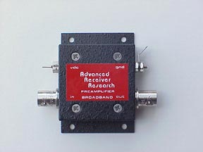
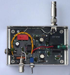
The two accompanying photos of
the RPA-1 are actually of my second unit, partly
modified, after I had completed the A/B testing
of one modified vs. one unmodified RPA-1 (a resounding
success.) The Antenna Input port (upper side in
both photos) is the factory-supplied F-connector
with a Type-F to BNC Adapter attached. On the lower
side of both photos, you will note the new BNC connector.
Possibly you can see the new power switch and its
bright yellow wiring and the green LED (red and
black wires.) The red rectangle is the bypass relay
and the two bright circles on the right are the
push-pull amplifier transistors. You may just be
able to discern the black heat sinks on these two
transistors, as well.
IN USE
The only receiver that I have
available to me right now is the WiNRADIO 303EP
"black box" receiver. It has both an excellent
S-meter marked in dBm and an active Spectrum Scope
which can be read in dB. Those two instruments clearly
indicate that the RPA-1, both modified and stock,
provides at least the 16 dB boost stated in the
manufacturer's specs. I don't have the sophisticated
instruments needed to test for the noise added to
a circuit by pre-amps. However, I have listened
carefully to both strong and weak, threshold-level
signals while flipping the RPA-1 in and out of the
circuit. I can't hear any added noise.
 |
The two illustrations on the
left are parts of screen shots of the WiNRADiO 303EP
while tuned to Radio Madang in Papua New Guinea
one recent dawn. The horizontal blue lines and the
words "Before" and "After" were
added by me later. The noise level in the unamplified
(BEFORE) example is -67 dB, and it rises to about
-51 dB with the amplifier turned on, a 16 dB improvement.
The same flip of the switch raised the signal strength
from -47 dB to -17 dB. I rush to add that some of
the increase in the noise figure was due to a momentary
surge in propagation conditions.
The improvement in the amount
of signal cresting above the noise can also, partly,
be attributed to that source. However, I have yet
to tune a weak signal on this antenna system that
has not shown a very noticeable improvement in the
quality and intelligibility the audio. This is true
as I tune either MW or the Tropical Bands.
I look forward to testing the
RPA-1 coupled to my 65' x 16' portable KAZ during
a future DXpedition to Grayland. I doubt that the
arrangement will outperform our much-vaunted Beverages,
but it might get close. In the meantime, I'm darn
sure glad that I bought two of these beauties!
2. MARK'S EXPERIENCE:
Since I often use my RPA-1 at
a position closer to the antenna (away from the
operating bench), I made a very simple modification
that lets me send 12 VDC up the coaxial line when
I want the amplifier on, and no DC up the line when
I want bypass. DC is fed onto the coaxial line at
the other end: the cable's connection at the DXP-6
phasing unit.
I took a 1.5 mH inductor and
wired it from the "RCVR OUTPUT" F connector
to the DC power input connector. The inductor used
was Bourns SDR1005-152J, Mouser stock number 652-SDR1005-152J.
It's a small surface mount piece resembling a miniature
hockey puck. I used short pieces of insulated wire
to connect the inductor (choke) between the normal
DC-in jack and the "RCVR OUTPUT" F jack.
I cut the direct connection between the "RCVR
OUTPUT" F jack and the otherwise redundant
adjacent RCA jack. I put a 0.1 uF capacitor from
the F to RCA jack so that the RCA "RCVR OUTPUT"
jack can be a pure RF connection not carrying DC.
This would be used when power is being applied at
the normal DC jack of the RPA-1.
The inductor allows DC on the
cable to power the amplifier even when it is being
fed from an operating position possibly hundreds
of feet away. I usually use the amplifier with my
car-rooftop antennas on beach DXpeditions or with
my Flag antenna at home.
I just use BNC to F adaptors
at both the ANTENNA INPUT and RCVR OUTPUT jacks.
If I power the RPA-1 at its own DC input jack, rather
than up the coax, I use a BNC to RCA jack for connecting
to the (RCA) RCVR OUTPUT jack that is now capacitively
coupled to the (F) RCVR OUTPUT jack.
Chris Black (N1CP) also has an
RPA-1 that he keeps near his receiver. I suggested
that he go to the hardware store and get one of
those inline switches typically used on lamp cords.
This switch is now on the cord going from the wall
wart to his RPA-1 DC input. No alteration of his
RPA-1 was required for the way he uses it in his
shack.
I should also note, although
the low end stated for the RPA-1 is given as 300
kHz, it can still provide usable gain lower in frequency.
With the Flag antenna at Chris Black's QTH in S.
Yarmouth, I got about 8 dB of gain at 150 kHz, 10
or 11 dB at 200 kHz, and better than 12 dB at 250
kHz. Usage, therefore, is still possible for the
typical frequency range of long wave broadcasters
and non-directional beacons.
A CAUTION
Internal modifications
to the RPA-1 like those noted in the first section
of the article will likely void whatever warranty
that DX Engineering offers with their fine equipment.
If you plan to modify an RPA-1, it would likely
be very prudent to run the amp under power for 12
or 24 hours first. Most early failures in solid
state gear occur in those first few hours. Should
one of those rare early failures occur, having the
RPA-1 fail before modifying it will let you return
the unit to DX Engineering for warranty work.
Published on July
12, 2005
  
|